Nearly every SCADA/ICS system is built around programmable logic controllers or PLC's. To understand the vulnerabilities of these systems, you must have some basic understanding of the programming of these systems.
In this tutorial, we will learn a bit of PLC ladder programming to help you understand the logic and programming of the essential PLC's in nearly all SCADA/ICS systems. without this basic knowledge of the PLC programming, hacking SCADA systems will be limited.
Ladder Logic is a programming language that represents a program by a graphical diagram based on the circuit diagrams of relay logic hardware. It is primarily used to develop software for programmable logic controllers (PLC's) used in industrial control applications. The name is based on the observation that programs in this language resemble ladders, with two vertical rails and a series of horizontal rungs between them.
From Wikipedia;
Ladder logic was originally a written method to document the design and construction of relay racks as used in manufacturing and process control.[1][2] Each device in the relay rack would be represented by a symbol on the ladder diagram with connections between those devices shown. In addition, other items external to the relay rack such as pumps, heaters, and so forth would also be shown on the ladder diagram... Ladder logic has evolved into a programming language that represents a program by a graphical diagram based on the circuit diagrams of relay logic hardware. Ladder logic is used to develop software for programmable logic controllers (PLCs) used in industrial control applications. The name is based on the observation that programs in this language resemble ladders, with two vertical rails and a series of horizontal rungs between them. While ladder diagrams were once the only available notation for recording programmable controller programs, today other forms are standardized in IEC 61131-3 (For example, as an alternative to the graphical ladder logic form, there is also a more assembly language like format called Instruction list within the IEC 61131-3 standard.).
The language itself can be seen as a set of connections between logical checks (contacts) and actuators (coils). This terminology is a holdover from the early SCADA systems that employed electro-mechanical systems.
If a path can be traced between the left side of the rung and the output--through asserted (true or "closed") contacts, the rung is true and the output coil storage bit is asserted (1) or true. If no path is traced, then the output is false (0) and the coil, by analogy to electromechanical systems, is considered de-energized. The analogy between logical propositions and relay contact status was first developed by Claude Shannon in his seminal work, A Symbolic Analysis of Relay and Switching Circuits.
Ladder Logic has contacts that make or break circuits to control coils. Each coil or contact corresponds to the status of a single bit in the PLC's memory. Unlike electro-mechanical relays, a ladder program can refer any number of times to the status of a single bit, equivalent to a relay with an infinitely large number of contacts.
So-called "contacts" may refer to physical ("hard") inputs to the PLC from physical devices such as push buttons and limit switches via an integrated or external input module, or may represent the status of internal storage bits which may be generated elsewhere in the program.
Each rung of the ladder language typically has one coil at the far right. Some manufacturers may allow more than one output coil on a rung.
The "coil" (output of a rung) may represent a physical output which operates some device connected to the programmable controller, or may represent an internal storage bit for use elsewhere in the program.
This lab will introduce you to Ladder Logic programming. We will be using Triangle Microworks --Trilogi educational software to become familiar with Ladder Logic programming.
Step #1 Download TRiLOGI Training Software.
First, install the i-TRiLOGI software on your Windows system. You can download it at www.triplc.com/iTrilogi6Edu/download.htm.
When it has completed the installation, Click on the "File" menu at top and select "New" and then click "Yes" to clear the current #Define table.
The password is LadderBasic2009.
Step #2 Open the Ladder Logic Trainer
You will now be in "Browser" mode on the logic editor. The vertical black line on the left of the screen is the "power" line. The cursor (red arrow) is at the position where we can key in your first ladder logic.

Before we start, though, we need to define what our inputs and outputs will be in this logic. We will be using the following values in this lab.

Let's open the I/O editor by clicking on the I/O Table button on the upper right side on the screen as seen below.

When you do so, a new window will open that enables you to enter all the circuit component information. The BLACK down arrow provides access to all the I/O labels. The two RED arrows allow you to scroll to different labels .
You can also use keyboard shortcuts to accomplish the same thing . F2 will open the I/O editor and the Left and Right arrow keys will enable you to scroll through the selections.
Entering data is very simple and can be accomplished in several ways with either the mouse or through the keyboard.
Let's begin by entering the Inputs like that below.
Select Inputs.

Then enter the data below.

Then select the outputs like this.

Then the relays and enter the data as seen below.

And the timers. Note that with the Timers we have to "Set Value". In this case we will set the value at 1000 . Each value is equal to .1 second, so this would be 100 seconds.

Finally, set the "Counters" as Seq1 and a value of 4. Now we are ready to begin to build our circuit!

To build our circuit, we will need to use several tools on the top ladder bar. The red arrow cursor is already positioned for circuit 1. To access the ladder bar, either double click the red arrow or click the arrow once and press the "Spacebar" on the keyboard. When you do so, the ladder bar menu will appear at the top of your screen like below.

Before we begin building our circuit, let's take a look at what each of the icons on the ladder bar mean.

N.O. Means Normally Open
N.C. Means Normally Closed
You can use right or left clicks to create open or closed circuits, respectively. Even if you forget this feature, you can use the element invert icon to change a component between open and closed.
Let's begin building our circuit. Start by double clicking the red arrow to enter edit mode. when you add a circuit component the I/O table will automatically open. You can then select the appropriate component label from the pull down menu.
Now, let's add a N.O circuit in series. left click the first icon as seen below. The I/O window will open. Select "Input" then "Start" and the first component will be placed on the screen.

Now, add a N.O. circuit in parallel. Left click on the second icon and select "Relay" and "Run" and the second component will be added.

The next component must be added to the "end" of the Start component. To accomplish this, click the right corner of the Start icon and it will become a yellow box. Now you can continue.
Add the next component a N.C. circuit in series. To do this, right click the first icon (series2) and then select "Input" and "Stop". Now we can add the Coil. Left click the fourth icon (coil7) and select "Relay" and then "Run". We are almost finished with the first circuit!
Finally, we need to add a coil in parallel. To do this, left click the fifth icon (coil8) and select "Timer" and then "Duration". The first circuit is now done!

To start the second circuit, click anywhere below the first circuit and second circuit will begin and the red arrow moves down.
Start by adding three N.O. circuit components in series (first icon) in this order-
Relay then Run, Input then Step, and Input then Manual.
We now need to add parallel circuits to both the Step and Manual. To do this, select "Step" circuit then hit "Shift" key--this changes the green box to the left side of "Step". Now, left click the third icon (parallel5) once. Notice the blue box and the red X that appeared on the left side of the Step component. Now click the Manual component and the click the third icon one more time. Select "Input" then "manual". The next component is in series to the N.C. Manual. Click the first icon. For this one will put in a clock. From the pull-down menu of the I/O labels, select "Special Bits" and .5s Clock.
Now to add the next component to the N.O. Manual component. Click the right corner of the top Manual component twice -- a yellow box should now be in the top corner. Next, let's add a function.
Click on the sixth icon (Fn9) and a new function window will appear. Select item 4 (Avseq) or Advanced sequencer. A new window will appear and select Sequencer 1.

We only have one sequencer is in this lab, to keep things simple. If we had multiple sequences (up to 8 are allowed), you could select the appropriate sequencer. This completes our second circuit. Click below the second circuit to begin our third circuit.

Step #4 Build Circuits 3,4,5 and 6
These circuits are very similar.
Circuit3
Start by adding a N.O. series component. Click the first icon (series 1). This time select "Special Bits, SeqN:x". This will open the sequence window. Select Sequencer1, we only have one. this will open the Step window; this is the first step, so type 1 and press enter.

Now add a coil. Select the fourth icon (coil7) and select "Output" and "out1". Then add a coil in parallel(fifth icon) and coil8 and then select "Output and then Out8.

On your own then, create circuits 4,5, and 6. When you are done, it should look like this.

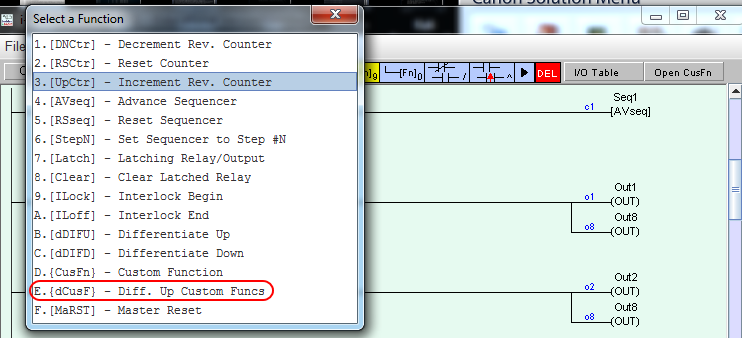
The last circuit is a bit different. This is an event counter circuit. We want this event to fire after every fourth Step through ladder. To start , add a N.O. series component. Click the first icon and select Special Bits, Seq:x" and then Sequencer1, Step4". Now we will add a custom function; click the sixth icon (Fn9) and select item "E. Diff Up Custom Funcs". This will open a new window.
The I/O label box will open. Click on the dark blue box and the new window will open. Type "Event Count" and press enter.

Let's then add some custom coding to this event. Double click the "Event Counter" component and new window will open.

Then type in the following code:
X=X+1 'Initial Value of X=0
setlcd 1,1, "Cycle Count="+str$(X)

Then click the red X in the upper right hand corner to close the window.
Now it is time to see if our lab works. Select "Simulate" and then "Run" (All I/O Reset). If there is an error, you will receive an error window from the software.
Congratulations on completing your very first Ladder Program for the PLC's in nearly every SCADA/ICS device!